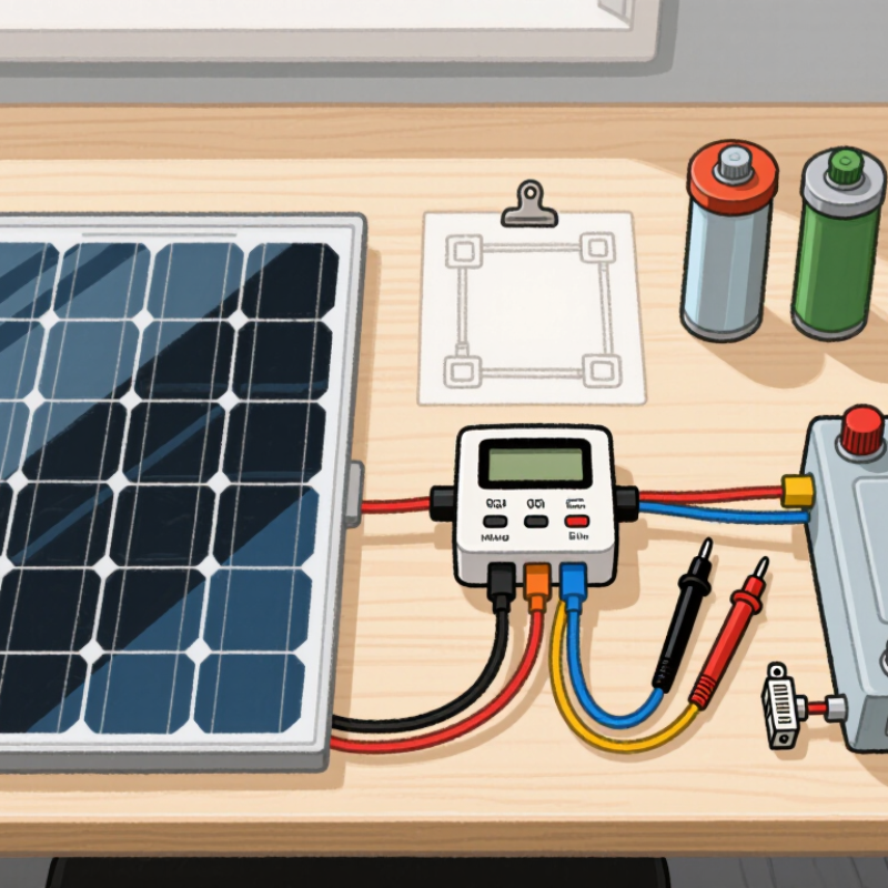
Learning how to connect a solar panel to a battery charger begins with one important distinction: a panel produces power, but it does not regulate battery charging. A suitable solar charge controller manages voltage, current, and charging stages. Without that control, a battery may overheat, charge unevenly, or suffer permanent damage.
Solar educator and battery specialist Will Prowse has emphasized, “A solar panel is not a battery charger.” This short statement explains the central safety issue. The panel, controller, battery, and cables must work as one system. Their voltage ratings must match. Their current limits matter too.
Before making connections, identify the battery chemistry. Lead-acid, AGM, gel, and lithium batteries require different charging profiles. Check the controller manual carefully. A multimeter can confirm polarity before the final connection. Red and black wires should never be trusted by color alone.
Small details matter.
A fuse near the battery can reduce fire risk during a short circuit. Use weather-resistant connectors outside. Keep exposed terminals covered. Never connect equipment while guessing.
This guide will explain How to connect a solar panel to a battery charger using practical steps and realistic checks. It will also address common mistakes, including reversed polarity, undersized cables, and unsuitable controllers. Some setups look simple but hide important limitations. I have found that the clearest wiring diagram can still mislead beginners if battery chemistry is ignored. Careful measurement remains more reliable than assumption.
How to Connect a Solar Panel to a Battery Charger?
Before connecting a solar panel, read its rating label carefully. Vmp means voltage at maximum power, while Imp means current at maximum power. Multiplying Vmp by Imp gives the panel’s approximate wattage under STC. For example, a panel rated at 18 Vmp and 5.5 Imp produces about 99 watts. STC assumes 1,000 W/m² sunlight, a 25°C cell temperature, and standard air conditions. Outdoor results are usually lower.
Voc is the open-circuit voltage measured without a load. It matters because cold weather can raise this voltage beyond the printed value. A charger’s solar-input limit must exceed the panel’s possible Voc, not only its Vmp. Otherwise, the charger may shut down or suffer damage. Check the charger’s maximum input current too. Imp should remain within that limit.
A panel labeled “12-volt” may have a Vmp near 18 volts, allowing battery charging through a suitable controller. Do not connect it directly to a battery unless the charging system is specifically designed for that method. In a practical check, compare the label with readings taken in bright sunlight, then expect some variation from heat, shade, and cable loss. I sometimes focus too much on wattage. That is a mistake. Voltage compatibility comes first. Recheck every limit.
How to Connect a Solar Panel to a Battery Charger?
A solar panel should feed a compatible charge controller, not the battery directly. Match the controller to the battery chemistry first. Lead-acid, lithium-ion, and lithium iron phosphate cells require different charging voltages and cutoff behavior. For example, a typical 12-volt lead-acid system may use absorption charging near 14.4–14.8 volts. A 12-volt lithium iron phosphate battery commonly needs about 14.2–14.6 volts. Always confirm the battery maker’s limits. Guessing here is unsafe.
Voltage matching is only one part. Check capacity and charging current. A 100-watt panel can theoretically deliver about 8.3 amps at 12 volts, before conversion losses. Real output changes with clouds, heat, shading, and panel angle. NREL’s PVWatts documentation uses a 14% default system-loss assumption, showing why nameplate power can mislead. Keep the controller’s maximum solar voltage above the panel’s cold-weather open-circuit voltage. Its output current must also stay within the battery’s approved charging rate.
Tips: Use a controller with chemistry-specific settings and temperature protection. Install a fuse close to the battery’s positive terminal. Verify polarity with a multimeter before connecting anything. Keep cables short and properly sized. The IEA PVPS reported global photovoltaic capacity passed 1.6 terawatts by the end of 2023, but larger deployment does not remove small-system risks. I still find one weak assumption common: “12 volts” is treated as a fixed voltage. It is not. Measure under real charging conditions.
| Battery Chemistry | Typical Nominal Voltage | Recommended Charging Voltage (12 V-Class System) |
Float Voltage | Typical Continuous Charge Current | Required Charge Controller | Temperature and Safety Considerations |
|---|---|---|---|---|---|---|
|
Flooded Lead-Acid Conventional wet-cell battery |
12 V 6 cells |
Absorption: approximately 14.4–14.8 V at 25°C | Approximately 13.2–13.8 V |
Commonly 0.10–0.20C Example: 10–20 A for a 100 Ah battery |
PWM or MPPT controller with a lead-acid profile | Charge in a well-ventilated area. Prevent overcharging, ignition sources, and electrolyte loss. Temperature compensation is important. |
|
AGM Lead-Acid Absorbent glass mat |
12 V 6 cells |
Absorption: approximately 14.2–14.6 V at 25°C | Approximately 13.2–13.6 V |
Commonly 0.10–0.20C Example: 10–20 A for a 100 Ah battery |
PWM or MPPT controller configured for AGM batteries | Do not use a flooded-battery equalization setting unless specifically permitted. Excessive voltage can cause permanent damage or venting. |
|
Gel Lead-Acid Valve-regulated gel electrolyte |
12 V 6 cells |
Absorption: approximately 14.0–14.2 V at 25°C | Approximately 13.5–13.8 V |
Commonly 0.10–0.15C Example: 10–15 A for a 100 Ah battery |
PWM or MPPT controller with a gel profile | Avoid overvoltage and equalization. Excessive charging voltage can create gas pockets and permanently reduce capacity. |
|
Lithium Iron Phosphate LiFePO₄, normally used with a BMS |
12.8 V nominal 4 cells in series |
Approximately 14.0–14.6 V, according to the battery specification | Usually disabled; if required, approximately 13.4–13.6 V |
Commonly 0.20–0.50C when permitted Example: 20–50 A for a 100 Ah battery |
MPPT or PWM controller with a lithium/LiFePO₄ profile and no equalization | Charging below 0°C is generally prohibited unless the battery includes approved low-temperature protection or heating. The BMS must provide overcharge, over-discharge, overcurrent, and temperature protection. |
|
Lithium-Ion NMC Nickel-manganese-cobalt chemistry |
Commonly 11.1–14.8 V for 3S or 4S packs Configuration-dependent |
Must match the exact series-cell configuration; a 4S pack commonly requires 16.8 V maximum | No continuous float charging unless specifically approved | Determined by the cell manufacturer and BMS; commonly 0.20–0.50C | A controller specifically programmed for the pack voltage and BMS requirements | Never connect a generic 12 V lead-acid charging profile without confirming the pack configuration. Use a certified BMS and the correct maximum charge voltage. |
Connecting a solar panel to a battery charger requires a charge controller between them. The controller regulates voltage and current, protecting the battery from overcharging. Check the panel’s open-circuit voltage and the battery’s charging voltage before wiring anything. Then connect the battery to the controller first, followed by the solar panel. This order reduces startup errors. Add a correctly rated fuse near the battery, and verify polarity carefully.
A PWM controller is simple and affordable. It works best when the panel voltage closely matches the battery voltage. However, it cannot fully use excess panel voltage. An MPPT controller converts that extra voltage into useful charging current. In cool weather, weak sunlight, or when panel voltage exceeds battery voltage, MPPT can deliver up to 30% more energy. That figure is possible, not guaranteed. Real gains depend on temperature, shading, cable loss, and panel configuration.
Small details matter. Keep cables short and suitably thick. Place the controller in a dry, ventilated location. Observe the battery manufacturer’s charging limits. I once assumed a higher-rated panel would always charge faster. That assumption was wrong. A poorly matched panel and controller can waste energy, even in bright sunlight. Measure charging current during different conditions, rather than trusting the label alone. unerquicklich
Estimated daily charging energy from a 100 W solar panel using PWM and MPPT controllers
Based on a 100 W panel and a 12 V battery system, the chart assumes controller conversion efficiencies of approximately 75% for PWM and 95% for MPPT. Under these assumptions, MPPT can provide up to 27% more usable charging energy. Actual results vary with panel voltage, battery state of charge, temperature, wiring losses, and shading.
Connecting a solar panel directly to a battery is unsafe. The charge controller must regulate voltage and prevent overcharging.
IEA PVPS Trends in Photovoltaic Applications 2024 reports more than 1.4 terawatts of global photovoltaic capacity. That scale reflects mature technology, not permission to skip wiring discipline. Use a controller rated above the panel’s maximum voltage and current. Check both figures in daylight conditions.
Wire the battery to the controller first. Place a properly sized fuse on the positive battery cable, close to the battery terminal. Then connect the panel’s positive and negative leads to the controller’s PV terminals. Connect the load afterward, if the controller supports one. During shutdown, disconnect the panel before the battery. Reverse polarity can damage equipment quickly. Fuse selection should match expected current, cable capacity, and local electrical requirements. A fuse is not a substitute for correct wire sizing.
Leave clear labels near every terminal. Measure polarity with a multimeter before tightening connections. National Renewable Energy Laboratory studies commonly use about 0.5% yearly photovoltaic degradation as a planning benchmark. Therefore, a system may produce less energy over time, but poor connections can cause much larger losses. I still recheck polarity twice; one rushed connection can erase careful design. Keep terminals dry, protected, and mechanically supported.
The sequence feels fussy. It is also the part most worth respecting.
How to Connect a Solar Panel to a Battery Charger?
Connect the solar panel to a suitable charge controller, not directly to the battery. The controller regulates fluctuating solar energy and protects the battery from overcharging. Confirm the panel’s voltage and current ratings before making connections. Place a properly rated fuse near the battery’s positive terminal. Check polarity carefully. A reversed connection can damage equipment within seconds.
Verify the charging voltage at the battery terminals while sunlight is available. For many 12-volt lead-acid batteries, the absorption voltage is about 14.4 V at room temperature. Lead-acid batteries may require temperature compensation, especially outdoors during cold weather. LiFePO4 batteries commonly use 14.6 V for full charging, but the battery manufacturer’s specification should control. Some systems require no continuous float charging.
Use a digital multimeter for confirmation. Measure directly across the battery terminals, not only at the controller display. Long cables can create voltage loss. I have found that a small reading difference can reveal loose terminals or undersized wiring. It is easy to overlook this. Also check whether the controller has a selectable battery profile. A lead-acid setting may apply unsuitable charging behavior to LiFePO4 chemistry. Leave ventilation around lead-acid batteries, and keep all connections dry and firmly tightened. Recheck the voltage after several minutes, because an initial reading may not represent the stable charging stage.
It regulates changing voltage and current. It also helps prevent battery overcharging and equipment damage.
Connect the battery to the controller first. Then connect the solar panel. This sequence reduces startup errors.
Check panel voltage, current, and battery charging limits. Add a correctly rated fuse near the battery’s positive terminal. Verify polarity carefully.
A PWM controller suits systems where panel voltage closely matches battery voltage. It is simple and affordable.
MPPT can use excess panel voltage as charging current. Gains may reach 30% in cool, shaded, or weak sunlight conditions.
No. Actual improvement depends on temperature, shading, cable loss, and panel configuration. The number is only possible.
Many systems use about 14.4 V during absorption charging. Outdoor systems may need temperature compensation.
Many systems use about 14.6 V for full charging. Follow the battery manufacturer’s specification instead of assuming.
Use a digital multimeter directly across the battery terminals. Measure during sunlight, then recheck after several minutes.
Keep cables short and thick enough. Use a dry, ventilated location. Tighten terminals and keep connections dry. Small losses matter.
No. I once assumed that. It was wrong. Poor matching can waste energy, even in bright sunlight.
How to connect a solar panel to a battery charger safely begins with checking the panel’s electrical ratings, including maximum power voltage (Vmp), open-circuit voltage (Voc), maximum power current (Imp), and wattage under standard test conditions. These figures must be compatible with the battery system and charge controller. Before wiring, confirm the battery’s chemistry, nominal voltage, capacity, and permitted charging current so the charging process remains safe and efficient.
Choose a PWM controller for a simple, economical setup, or an MPPT controller when you want to capture more available energy, potentially gaining up to 30% more in suitable conditions. Connect the battery to the controller first, then connect the solar panel, using the correct polarity and an appropriately rated fuse near the battery. Finally, verify the charging voltage with a meter: a typical lead-acid battery may require about 14.4 V, while a LiFePO4 battery commonly uses around 14.6 V, subject to the manufacturer’s specifications.

E-Tronde Charger